Pippin's announcement of a new tool to use buttons and rotary encoders on a Raspberry Pi inspired me have a play with hardware controls for a Pi-based player, and since I'm planning to build an integrated amplifier (based on Hypex amps and their DLCP DSP board), I thought I'd combine the two and build a Raspberry Pi into the enclosure and make it the default source. 'Paul-' has been further developing the button daemon, and it's turning into a powerful tool.
I thought I'd try to make a control panel for the RPi that would match or mirror the DLCP control panel.
![]()
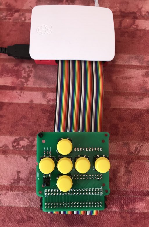
My idea was to connect the panel to the RPi via a ribbon cable so that the button panel could sit behind the amp's front panel, and the RPi could be mounted elsewhere inside the enclosure.
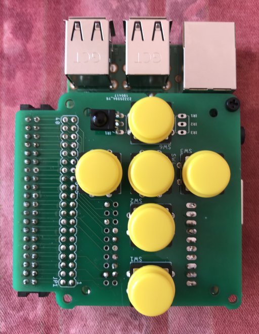
Hypex were kind enough to give me details of the switches and button caps that they use (they really are very focused on the DIY market). They also supply CAD drawings of their DLCP control panel, so I used the measurements to draw up a simple circuit board (my first!) and had some samples made. I included a couple of spaces for an IR receiver, so that the panel could be made to exactly match the DLCP or, the other way up, to mirror it.
![]()
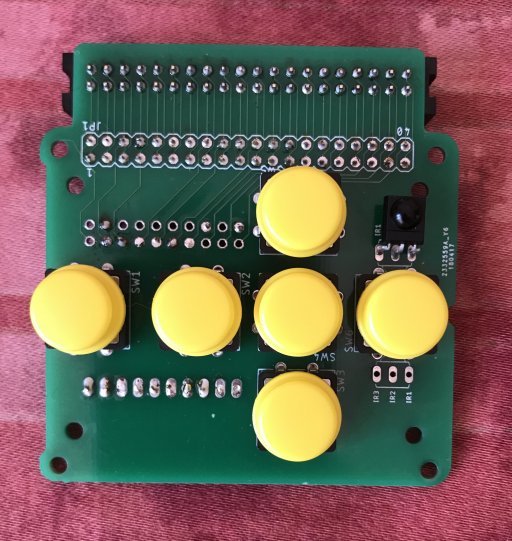
The samples arrived today, so I built one up.
![]()
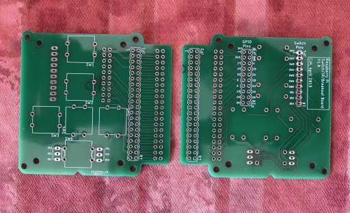
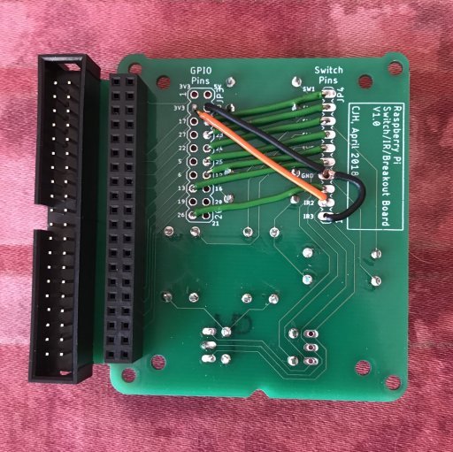
The idea was to install pin headers into the 'GPIO Pins' and 'Switch Pins' locations so that I could experiment with different GPIO configurations, but while I was waiting for the boards to arrive I finalised which pins I wanted to use so I hardwired this board. The pins I've chosen avoid the ones commonly used by the HiFiBerry add-on amps and DACs.
![]()
The underside of the board carries a socket so that the board can mount directly to the RPi, hat-style (it's not a hat, as it doesn't have an EPROM to identify itself to the RPi, but the mounting holes are at the right spacing to mount hat-style). I also included a box header so that the board could be mounted on a ribbon cable, or alternatively so that other devices (amp, DAC etc) could be daisy-chained. With the board mounted on top of the RPi it gives me a convenient place to hang the RPi inside my amplifier enclosure - no need for a separate location or a ribbon cable - it'll just hang off the button board behind the front panel.
![]()
![]()
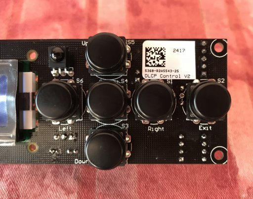
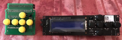
Here's the built-up board next to its inspiration.
![]()
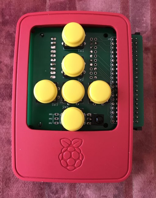
By luck, the button arrangement fits perfectly within the cutout in the lid of the official RPi case, so I made sure the board would fit inside the case (hence all the little shaping details). I'm considering having some made without the box header tab on the side, or possible making the tab a snap-off section, so that it fits entirely within the case. There's no reason why I couldn't simply saw off the tab on the existing boards though.
![]()
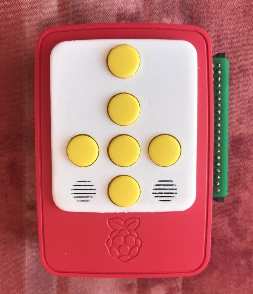
I also made a little clip-in panel on my 3D printer. I quite like the 'Fisher-Price' look of the red-and-white case with yellow buttons. :)
I included 'grilles' in front of the IR receiver locations, but in fact they're not really needed as the IR gets through the PLA clip-in panel.
![]()
I thought I'd try to make a control panel for the RPi that would match or mirror the DLCP control panel.
My idea was to connect the panel to the RPi via a ribbon cable so that the button panel could sit behind the amp's front panel, and the RPi could be mounted elsewhere inside the enclosure.
Hypex were kind enough to give me details of the switches and button caps that they use (they really are very focused on the DIY market). They also supply CAD drawings of their DLCP control panel, so I used the measurements to draw up a simple circuit board (my first!) and had some samples made. I included a couple of spaces for an IR receiver, so that the panel could be made to exactly match the DLCP or, the other way up, to mirror it.
The samples arrived today, so I built one up.
The idea was to install pin headers into the 'GPIO Pins' and 'Switch Pins' locations so that I could experiment with different GPIO configurations, but while I was waiting for the boards to arrive I finalised which pins I wanted to use so I hardwired this board. The pins I've chosen avoid the ones commonly used by the HiFiBerry add-on amps and DACs.
The underside of the board carries a socket so that the board can mount directly to the RPi, hat-style (it's not a hat, as it doesn't have an EPROM to identify itself to the RPi, but the mounting holes are at the right spacing to mount hat-style). I also included a box header so that the board could be mounted on a ribbon cable, or alternatively so that other devices (amp, DAC etc) could be daisy-chained. With the board mounted on top of the RPi it gives me a convenient place to hang the RPi inside my amplifier enclosure - no need for a separate location or a ribbon cable - it'll just hang off the button board behind the front panel.
Here's the built-up board next to its inspiration.
By luck, the button arrangement fits perfectly within the cutout in the lid of the official RPi case, so I made sure the board would fit inside the case (hence all the little shaping details). I'm considering having some made without the box header tab on the side, or possible making the tab a snap-off section, so that it fits entirely within the case. There's no reason why I couldn't simply saw off the tab on the existing boards though.
I also made a little clip-in panel on my 3D printer. I quite like the 'Fisher-Price' look of the red-and-white case with yellow buttons. :)
I included 'grilles' in front of the IR receiver locations, but in fact they're not really needed as the IR gets through the PLA clip-in panel.